GCode Plotter
Building a GCode pen plotter
Before I begin, I want to credit Louis from the YouTube channel DIY Machines. I built this project by following his Arduino CNC drawing machine guide. The video can be found here.
I have never been great at drawing by hand, but I wondered whether I could still create that hand-drawn pen effect through an automated process.
After my family gifted me a 3D printer, I learned how these machines read GCode: a set of coordinate-based instructions that turns a digital file into physical motion. Rather than only reading about the coordinate math behind it, I decided to replace the extruder with a pen and build a plotter around the same idea.
The GCode Plotter reads GCode and turns it into physical drawings. Give it a GCode file and it moves a pen across two axes to recreate the encoded path, from simple shapes and text to detailed vector illustrations.
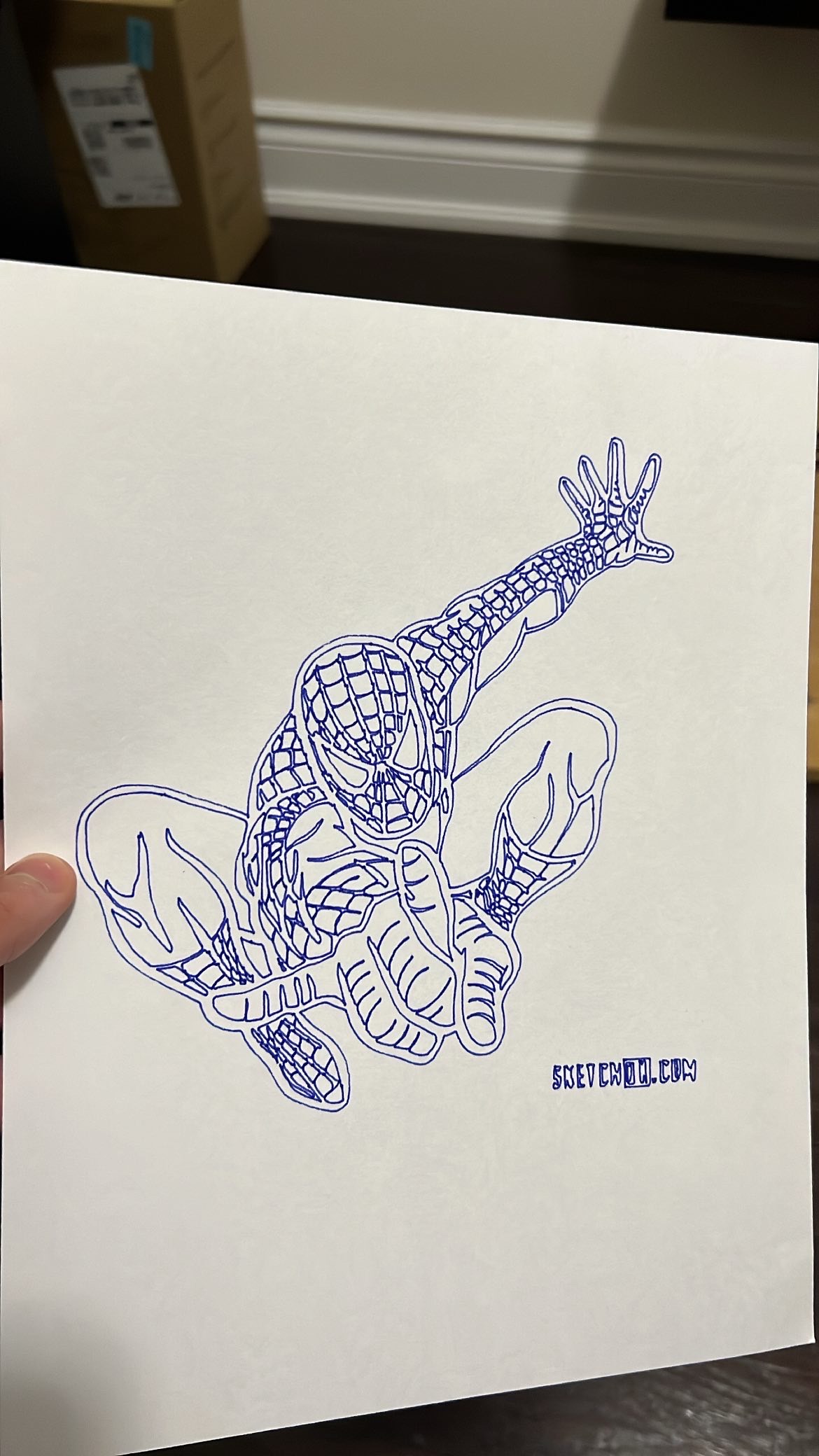
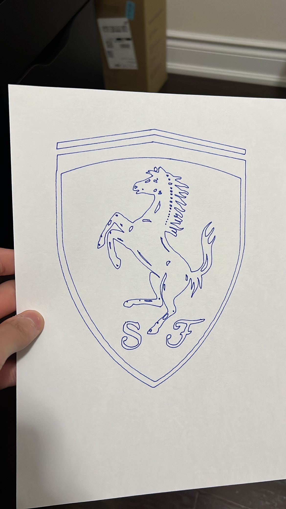
How the plotter draws
At its core, the plotter runs GRBL, open-source CNC control firmware flashed onto an Arduino Uno. GRBL interprets the GCode line by line and translates each movement command into precise step signals for the motors.
Two NEMA 17 stepper motors, driven through timing belts and pulleys, move the pen carriage along the X and Y axes. The carriage rides on linear bearings and 8 mm steel rods to keep its motion smooth across the drawing plane.
A micro servo handles the pen lift, acting as the Z axis by raising the pen between strokes and lowering it only when the machine should draw. Tuning the servo height took trial and error: sometimes it would not lower far enough to reach the paper, while other settings made it press too hard.
Contact switches at the end of each axis define the machine's X and Y limits so the motors never attempt to move beyond the plotter's physical range.
Video: The mini servo in action: raising and lowering the pen between strokes. Open video file.
From SVG to GCode
Artwork starts as an SVG, which I trace and convert into GCode paths using Inkscape. The generated GCode is sent over serial to the Arduino, which executes it line by line in real time while moving and lifting the pen to recreate the original path. The workflow is similar to sending an STL file to a 3D printer, except the output is ink on paper.
Tech stack
Firmware: GRBL on Arduino Uno
Motion control: 2x NEMA 17 stepper motors, TMC2208 drivers, Arduino CNC shield
Mechanical: GT2 belts and pulleys, linear bearings, 8 mm steel rods, micro servo for pen lift
Homing/safety: 2x contact switch limit switches
GCode generation: Inkscape for SVG-to-GCode path conversion
Power: 12 V power supply
Build/deploy: 3D-printed frame, Arduino IDE for flashing firmware
Takeaways
I usually build software projects, so working on something hardware-based pushed me out of my comfort zone. Watching software and mechanics synchronize to produce something physical gave me a different kind of satisfaction from shipping code, and it opened me up to taking on more hardware projects.
The biggest lesson was how differently I had to debug. In software, a bug is usually a logic error that can be traced and fixed with certainty. In hardware, the same code can behave differently depending on friction, tolerance, alignment, or wear. Getting the plotter working reliably meant iterating through physical trial and error instead of reasoning from code alone.
